A crane rated for the weight of your heaviest load can still be unsuitable if the load spectrum, hook height, runway forces, duty cycle or operating environment falls outside its design basis. By the end, you will be able to turn a plant drawing and production data into a crane specification that covers capacity, coverage, controls, structure, safety and future expansion.
Key takeaways
- Include every attachment and impact factor in the rated load calculation.
- Measure the usable hook envelope from the plant drawing, not floor dimensions.
- Match crane type to coverage, building structure and future relocation plans.
- Require documented runway, electrical, control, safety and maintenance specifications.
Define Capacity by the Complete Load Path and Duty Cycle
1. Do not choose a crane from the heaviest product weight alone. Define the maximum suspended load, including the lifting beam, spreader, magnet, grab, hook block and other attachments, then account for impact loading, load imbalance and planned future expansion.
A 5-tonne crane is not automatically suitable for a 5-tonne lift: a 5-tonne attachment leaves no capacity for the material.
2. Trace the complete load path: crane bridge, hoist, trolley, hook, sling points and every below-the-hook device. The safe working load or rated load marked on any component can limit the system. Obtain the rated load of each attachment before finalizing the crane rating, and treat the lowest-rated component as the controlling limit.
3. Specify the load spectrum with operating data: lifts per hour, average lifted load, percentage of lifts near rated capacity, loaded travel distance, shifts per day and peak loads. Use these inputs to select a CMAA classification and an ISO 4301 utilization class.
Occasional maintenance lifting needs a different duty basis from continuous production service, even at the same maximum load.
4. Record future production increases before ordering. More shifts, longer travel, faster cycles or frequent near-capacity lifts can require a higher duty class and stronger components, not merely a larger nameplate capacity.
Calculate the Usable Hook Envelope from the Plant Drawing
A plant drawing gives you usable hook height only after you subtract the space occupied by the building and hoisting equipment. Measure the floor-to-roof clearance, runway elevation, beam depth, trolley and hoist headroom, then calculate: usable hook height = available vertical envelope − structural headroom − hoist headroom.
Mark these dimensions on both plan and elevation drawings:
- Minimum and maximum hook height, plus the pickup and set-down elevations that determine required hook travel.
- Hook approaches at both ends, crane span, trolley travel and column positions.
- Pits, trucks, fixtures, loading docks and every obstruction zone.
- Roof interference, service-platform interference and the lowest obstruction below the runway.
- Building services such as ducts, pipes, cable trays, sprinklers and lights that the hook, load or trolley must clear.
Required hook travel must cover the full vertical difference between the lowest pickup and highest placement point, with clearance for the load and lifting attachment. State the minimum end approach at each end, maximum and minimum hook height, trolley travel, roof and service-platform interference, and lowest obstruction in the specification.
Nominal span and tonnage do not prove access. The hook must reach the real pickup and placement points without striking columns, equipment, vehicles or building services. A crane that cannot enter the required envelope cannot perform the lift.
Match the Crane Type to Coverage, Structure and Relocation Needs
Choose the crane type by matching span, duty cycle, hook approach and coverage with the building and floor available.
| Option | Compare these factors | Best fit |
|---|---|---|
| Single-girder EOT crane | Moderate span and duty; lower self-weight and headroom demand | Permanent runway with repeatable production coverage |
| Double-girder EOT crane | Longer span, heavier duty and improved hook height; higher runway reactions | High-cycle lifting, wide bays or large hook loads |
| Gantry crane | Ground-supported legs, clear overhead space and dedicated travel path; needs floor capacity and alignment | Sites without usable runway beams or with outdoor exposure |
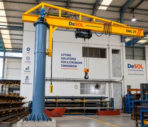
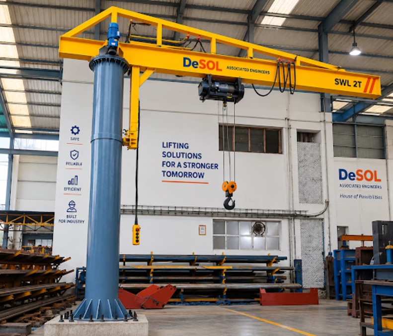
| Jib crane | Short reach and concentrated coverage; limited rotation and load area | One workstation, loading point or machine |
| Mobile crane | Relocatable lifting point; setup, outriggers and ground bearing govern | Changing positions where setup time is acceptable |
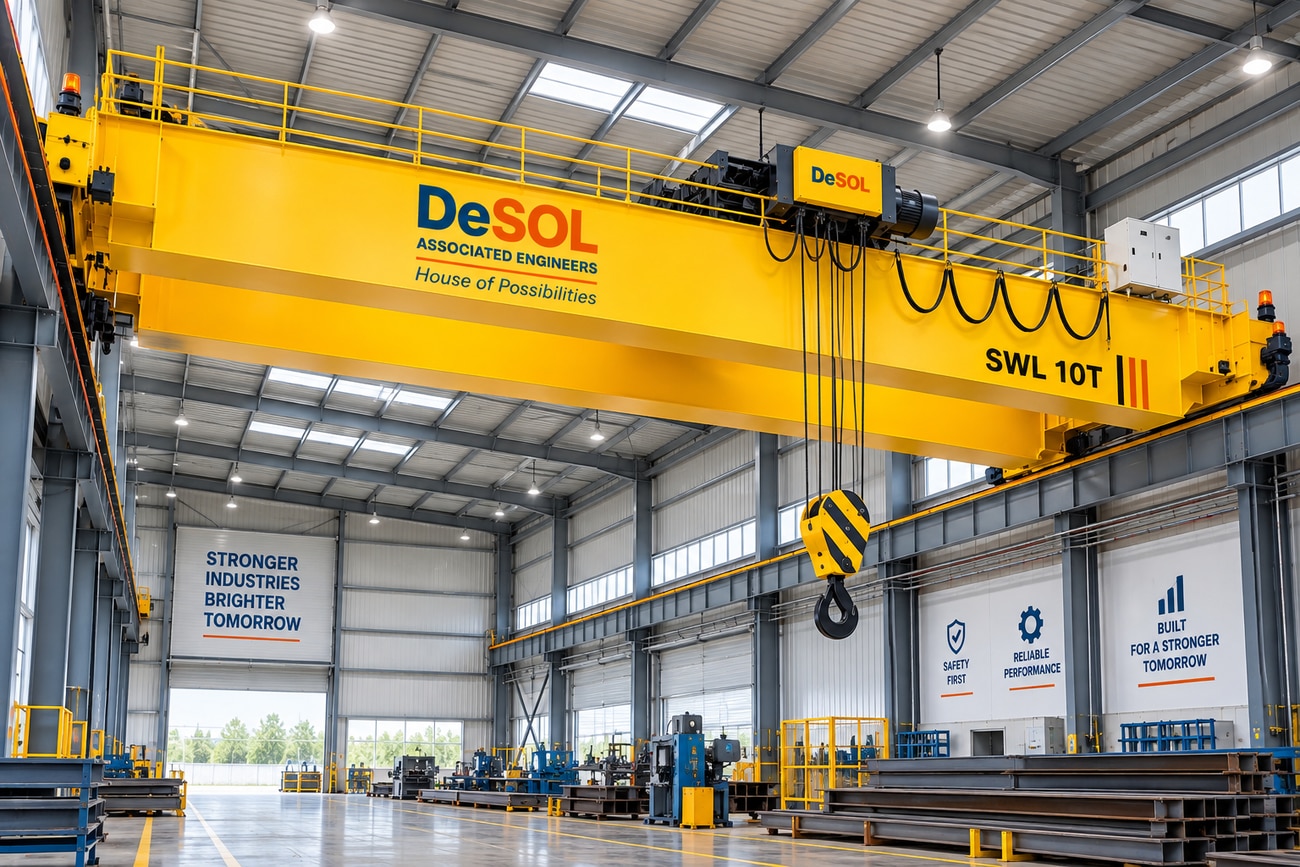
Use an EOT arrangement when a verified permanent runway gives broad, repeatable coverage. Check end approaches, columns, roof services and trolley access; nominal span does not prove the hook reaches every pickup point.
A gantry crane or freestanding jib crane can avoid modifying building columns, beams and connections, but transfers wheel or leg reactions to the floor and foundations. An overhead system requires verified runway beams, rails, columns, connections and fatigue capacity.
Fixed cranes deliver faster, repeatable cycles; mobile equipment buys relocation flexibility at the cost of setup time, floor preparation and productivity. Outdoor choices also require wind, rain, corrosion and storm-parking provisions.
Specify Hoist, Travel, Control and Safety Performance Together
Specify lifting, cross-travel and long-travel speeds with acceleration, deceleration, stopping distance, sway control, allowable placement tolerance and complete pick-to-set-down cycle time. A higher top speed fails to improve output if swing delays placement.
| Hoist choice | Best fit | Check before selection |
|---|---|---|
| Wire-rope hoist | Higher lifts, larger loads and heavier production duty | Drum, sheaves, headroom and maintenance access |
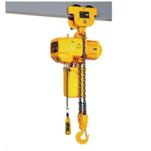
| Chain hoist | Shorter lifts, compact geometry and lighter or intermittent duty | Chain path, load size, duty rating and access for chain inspection |
A variable-frequency drive gives smoother starts, controlled positioning and lower mechanical stress. It does not replace a correctly sized mechanical brake, overload protection, thermal evaluation, or a defined loss-of-power and drive-fault response; specify a braking resistor when regenerative energy requires dissipation.
| Control choice | Main checks |
|---|---|
| Pendant | Sight lines, operator access and supported cable |
| Radio | Interference, frequency management, battery changes and lost-signal fail-safe |
| Cab | Broad visibility, protected access and emergency egress |
Specify normal stopping separately from protective devices: independently verify upper and lower limit switches, emergency stop, travel limits, anti-collision devices, audible or visual alarms and overload protection against site risks. An upper hoist limit switch protects against overtravel; it is not a normal positioning control.
Verify Runway, Building, Electrical and Environmental Compatibility
1. Verify the complete runway and building interface before ordering the crane. Check rails, runway beams, columns, foundations, rail attachments, end stops and building connections for vertical wheel loads, horizontal surge and tractive forces, fatigue, deflection and skewing. A structure that carries static crane weight may still fail under repeated wheel loads and lateral forces.
2. Name the responsible structural engineer, or define another qualified party, to approve the building interface. Require calculations for crane reactions, connections and foundations; do not rely on the building’s existing static capacity alone.
3. Record the electrical supply in writing: voltage, phase, frequency, available short-circuit current, grounding arrangement, disconnect location and environment, control voltage, conductor or festoon system, collector arrangement, voltage drop, and braking or regenerative-energy treatment. Include motor current and any braking resistor requirement.
4. Separate indoor and outdoor design cases. For outdoor service, define operating wind, out-of-service wind, storm parking, rail clamps, rain ingress, icing, lightning, solar load and corrosion protection. For dust, moisture, heat or corrosive atmospheres, specify enclosure protection and materials.
Before selecting electrical equipment for a hazardous area classification, provide the zone or division, gas or dust group and temperature class. Ordinary enclosed equipment is not automatically suitable.
Turn the Decision into a Verifiable Procurement and Maintenance Specification
Before comparing proposals, issue a crane procurement specification that fixes the duty, site constraints and acceptance evidence:
- Rated capacity, maximum load, load spectrum, CMAA or ISO 4301 duty class, lift and travel speeds, cycle time, placement tolerance and future capacity.
- Hook envelope, minimum end approaches, headroom, clearances, runway reactions, electrical supply, environmental classification, controls and safety devices.
- Drawings showing wheel loads, end-carriage clearances, hook approaches, headroom, conductor or festoon routing, access platforms and maintenance zones.
- Named responsibility for runway verification and building-structure approval. Do not assume the supplier owns inaccurate plant dimensions.
- Test records for overload protection, brakes, upper and lower limit switches, emergency stop and control-loss response. Test the upper hoist limit under no load; it is protective, not normal positioning control.
- Access to drums, sheaves, gearboxes, collectors, panels and brakes, with inspection intervals and spare-part lead times. Poor maintenance access increases downtime and inspection risk.
| Item | Record | Verify |
|---|---|---|
| Duty | Lifts per hour, load percentage, shifts and travel distance | CMAA or ISO 4301 class |
| Performance | Speed, acceleration, stopping and tolerance | Complete pick-to-set-down cycle |
| Structure | Wheel loads and runway reactions | Named structural verifier |
| Environment | Indoor/outdoor or hazardous-area classification | Motors, enclosures and controls |
Desol Associated Engineers can translate measured clearances and operating data into a coordinated proposal, while you retain responsibility for site accuracy and structural approval.
Related products
 | EOT Crane / Overhead Crane / Industrial Lifting Equipment EOT Crane is a heavy-duty overhead material handling solution designed for lifting, lowering and horizontal movement of heavy loads across industrial... View product → |
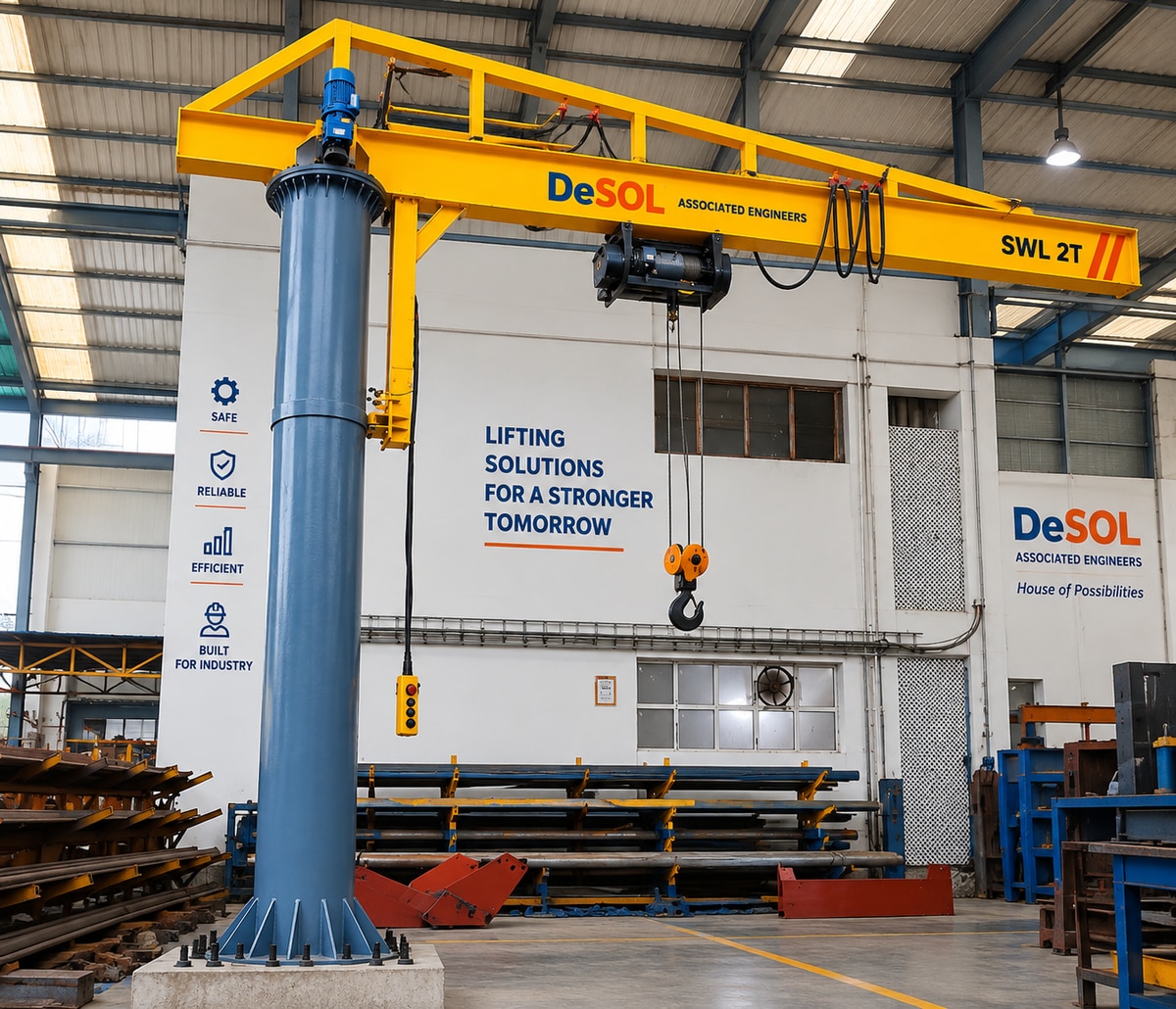 | Jib Crane / Pillar Mounted Crane / Material Handling Equipment Pillar Mounted Jib Crane is a heavy-duty material handling solution designed for efficient lifting and positioning of loads within a defined working... View product → |
Frequently asked questions
How should you define a crane’s required capacity?
Calculate the complete suspended load: product, lifting beam, spreader, magnet, grab, hook block and attachments. Add impact loading, imbalance and planned expansion, then select the duty class for the operating cycle.
How do you calculate the usable hook envelope?
Use the plant drawing to check hook height, side reach, end approach, runway length, obstructions, floor clearances and access points. The usable envelope is the area the hook can safely reach, not the building’s total floor area.
Which crane type should you choose for an industrial application?
Compare overhead, gantry, jib and other crane arrangements against required coverage, available structure, load paths, headroom, installation limits and whether the equipment must move or be relocated.
What must a crane procurement specification include?
Specify capacity, duty cycle, hoist speed, bridge and trolley speeds, control method, braking, safety devices, runway requirements, power supply, environmental conditions, inspection records and preventive-maintenance responsibilities.