A crane can have the correct rated capacity and still operate unsafely if its runway, foundation, controls, clearances or protective devices are wrong. By the end, you will know what an installer must verify before erection, what commissioning records to demand, and which operating symptoms indicate an installation defect rather than normal break-in.
Key takeaways
- Complete a site survey before delivery and confirm every load path.
- Obtain structural calculations for columns, runway beams, brackets and foundations.
- Record alignment, electrical, limit-switch and emergency-stop checks during commissioning.
- Reject handover without signed load-test results, inspection records and operating documents.
What must be verified before the crane arrives?
A site survey is the first safety control because it exposes a bad load path before equipment, riggers and lifting gear reach the site. A crane with the correct rated capacity remains unsafe if the building columns, runway beams, brackets, foundations or connections cannot carry its operating loads.
1. Provide the crane layout drawings, rated capacity, span, lift height and headroom, runway length, hook approach requirements, and the equipment’s weight and wheel-load data.
2. Record runway-girder levels, rail spacing, column positions, floor levels, foundation dimensions, concrete condition, anchor-bolt locations, overhead obstructions and required clearances. Confirm that the measured structure matches the drawings.
3. Identify the power-supply voltage and phase, disconnect location, conductor route, control-station position, access for delivery vehicles, lifting points, assembly space and exclusion zones.
4. Have the installer identify the governing specification and manufacturer’s runway tolerances before acceptance. Do not copy limits from another crane type; wheel arrangement, runway design and contractual requirements change the allowable values.
5. Approve every capacity change or field modification in writing through the manufacturer or a qualified person, then update the rated-load marking where required.
6. Plan temporary conditions before mobilisation. Partially bolted joints, unsupported rails, loose end stops, incomplete conductors and temporary lifting arrangements can cause accidents that a final operational test will not reveal.
Keep the survey, drawings, measurements and restrictions as the installation baseline. That record makes later skewing, brake drift, vibration or wheel damage traceable.
How do you prove the building or foundation can carry the crane?
Require a qualified structural engineer to verify the complete load path, not just the crane’s rated capacity. The calculation must trace forces from the lifted load through the hook, hoist, bridge or jib, runway or pillar, connections, concrete, soil and foundation.
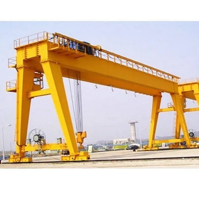
1. Obtain the crane manufacturer’s wheel loads, end-truck spacing, span, lifted-load capacity, hoist and trolley weights, travel speeds, impact factors and braking forces. Check vertical, lateral, longitudinal, impact and dynamic loads against the governing design code and the actual operating duty.
2. For an EOT crane, verify runway-girder alignment, rail elevation, rail size, brackets, connections, end stops and building-column capacity. Confirm that columns, roof or wall framing, foundations and anchorages resist wheel loads plus horizontal surge and braking forces. A visibly straight runway can still skew the bridge, overload wheels and damage brakes.
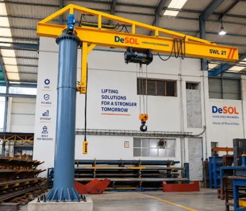
3. For a pillar-mounted jib crane, verify the concrete foundation condition, pedestal or pillar section, base-plate thickness, welds, reinforcement and soil bearing capacity. Check the anchor-bolt layout against the manufacturer’s template, level the base plate, and calculate overturning, uplift, shear and torsion from the maximum outreach and braking.
4. Record survey readings, concrete defects, bolt dimensions, steel sizes and connection conditions before erection. Reject cracked concrete, missing reinforcement information, distorted plates or loose anchors until an engineer approves a repair.
5. Keep temporary lifting arrangements, partially bolted joints and unsupported rails controlled. A proof or operational load test cannot correct a deficient structure or bad geometry; retain the signed calculations, survey and test records as the acceptance baseline.
What happens during mechanical erection, electrical connection and alignment?
1. Start with a delivery inspection. Match the crane, hoist, end carriages, wheels, ropes, hooks, controls and fasteners against the drawings and packing list; record damage, missing parts and serial numbers before lifting anything. Keep temporary lifting arrangements, partially bolted joints and unsupported components controlled and barricaded.
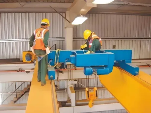
2. Mechanical erection follows the approved sequence. Assemble the bridge, end carriages and hoist for an EOT crane, then install runway rails, joints, brackets and end stops. For a pillar-mounted jib crane, set the foundation anchors, perform base-plate levelling, torque the anchor bolts and assemble the pillar, boom and rotation mechanism.
3. The electrical connection begins with the incoming supply and lockable disconnect. Install conductor bars or festoon cables, collectors, grounding conductors and protective covers; then connect the pendant or radio receiver, control panel, motors and control wiring. Verify phase sequence, earth continuity, cable support and isolation before energising.
4. Alignment uses a runway survey for rail gauge, elevation, straightness, span and end-stop position. Check wheel contact, bridge skew, pillar plumb, boom swing clearance, hook approach distances and overhead obstructions. Incorrect geometry causes wheel flange wear, binding, diagonal travel and excessive motor load.
5. Adjust travel, hoist and trolley limit switches at slow speed, leaving the upper hoist limit as a protective device rather than a routine stopping control. Confirm emergency-stop response, controls, brakes and clearances, then record unloaded and loaded observations, settings, survey results, restrictions and corrections as the installation baseline.
Which commissioning checks and load-test records prove the crane is ready?
Readiness is proven by a signed commissioning record, not by a crane lifting one load. The record should show brake holding, hoist and travel limit-switch operation, emergency stop response, control direction, overload protection, and the condition of the complete load path.
A load test cannot correct a weak runway, defective end stop, poor grounding, or incorrect control settings.
Commissioning observations should record:
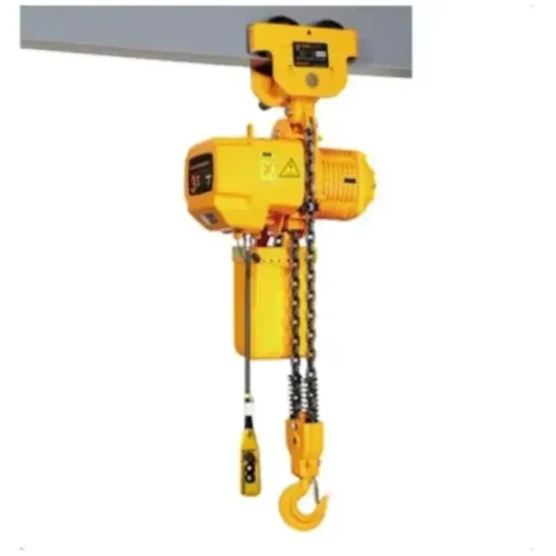
- Hook condition, latch, wire-rope seating, reeving pattern, rope termination, drum winding, and hook block movement.
- Hoist upper and lower limit switches, bridge and trolley travel limits, clearances, and end-stop condition. Treat the upper limit as protective; use the normal control to stop production movements.
- Brake holding without drift, even braking, emergency stop response, pendant or radio commands, phase sequence, grounding, disconnect operation, and control voltage.
- Overload protection trip point or verified function under the selected code or site procedure; do not defeat it to complete the test.
- Wheel tracking, rail contact, skewing, unusual noise, vibration, rubbing, and unloaded versus loaded travel observations.
| Test type | What the record must show | Use |
|---|---|---|
| Operational test | Rated-capacity identification, motions tested, speeds, limit and stop responses, control direction, brake holding, observations, defects, and restrictions | Routine acceptance under the site procedure |
| Proof load test | Selected code or procedure, test load and calibration, load position, duration, motions, deflection or drift readings, inspector, date, result, and corrective actions | Required when specified for acceptance |
Attach the runway survey, settings, test certificates, photographs, and signed approval. A baseline makes later brake drift, vibration, skewing, or wheel damage measurable.
How can you recognise a poor installation after handover?
Treat the handover readings as your baseline, not a formality. Compare later behaviour with the runway survey, specified runway tolerances, unloaded and loaded observations, brake settings, limit-switch positions, control response, and the crane’s safe working load. A crane that looks straight can still skew or overload one end truck.
- Bridge travel that scrapes wheel flanges, pulls sideways, or leaves polished rail marks indicates skewing or rail misalignment.
- Deflection beyond the recorded unloaded-to-loaded movement, persistent vibration, or new wheel damage requires measurement against the commissioning baseline.
- A hoist or bridge that creeps after releasing the control indicates drifting; stopping distances that differ between directions indicate uneven braking.
- Recheck anchor bolts for looseness, shifted washers, cracked grout, or base-plate movement before operating a pillar-mounted crane.
- Inspect festoon cables, pendant cables, conductor bars, guards, and cable glands for cuts, crushing, exposed conductors, or heat damage.
- Oil beneath gearboxes, brakes, hydraulic components, or couplings identifies a leak; clean the area and trace the source rather than topping up fluid.
- Any uncommanded hoist, bridge, trolley, or jib movement requires an immediate stop, isolation, and control-circuit investigation.
Require handover records containing drawings, test results, settings, defects, restrictions, and inspection intervals. A provider such as Desol Associated Engineers should issue a dated corrective action plan naming each defect, owner, deadline, isolation requirement, and retest result. Do not accept “adjusted” without evidence.
Related products
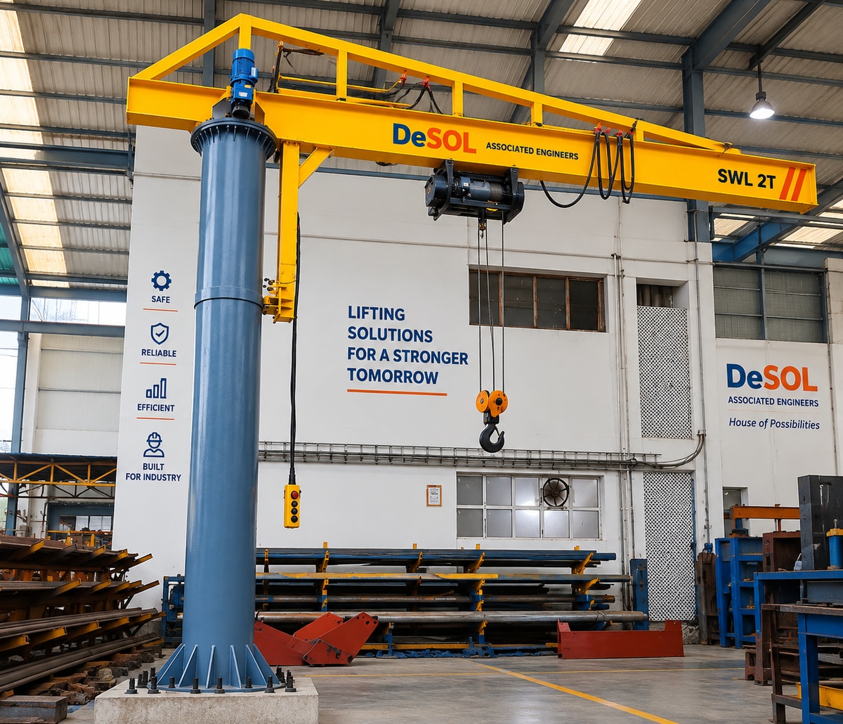 | Jib Crane / Pillar Mounted Crane / Material Handling Equipment Pillar Mounted Jib Crane is a heavy-duty material handling solution designed for efficient lifting and positioning of loads within a defined working... View product → |
 | EOT Crane / Overhead Crane / Industrial Lifting Equipment EOT Crane is a heavy-duty overhead material handling solution designed for lifting, lowering and horizontal movement of heavy loads across industrial... View product → |
Frequently asked questions
What must be verified before the crane arrives?
Verify the site dimensions, access route, lifting plan, power supply, runway geometry, foundation condition and approved installation drawings before delivery.
How do you prove the building or foundation can carry the crane?
Use signed structural calculations and drawings that address crane dead load, lifted load, wheel loads, impact, lateral forces, runway reactions and connection capacity.
What happens during mechanical erection, electrical connection and alignment?
The installation team erects the bridge, end carriages, hoists, runway components and guards, then connects controls and power before checking rail gauge, level, squareness, travel and hoist alignment.
Which commissioning checks and load-test records prove the crane is ready?
Keep records of no-load and rated-load tests, brake performance, limit switches, emergency stops, controls, travel, hoisting, deflection and any overload test required by the approved procedure.
How can you recognise a poor installation after handover?
Look for skewing, rail noise, drift after braking, uneven lifting, damaged cables, loose fasteners, missing guards, unreliable limit switches and incomplete inspection or test records.